PRE - ENGINEERED STEEL BUILDING
DECKING, STUD, SCREW
BMB DECK functions as formworks in construction stage and combined with reinforced concrete as composite slab in completed stage. There are many transversal embossments distributted equally along longitudinal panel which increasing the stiffness as well as strength of decking panel.
BMB DECK is designed following codes : ANSI-C2017 Standard for Composite Steel Floor Deck-Slabs and AISI S100 North American Specification for the Design of Cold-Formed Steel Structural Members.
BMB decking panel shall have 50mm/75mm deep major ribs and are spaced 334mm/287mm on center. Additional minor stiffening ribs are located in the middle of major ribs. Each panel shall provide 1000mm/870mm cover width and thickness 0.75mm, 0.95mm, 1.15mm.
| Size | H (mm) |
S (mm) |
W (mm) |
|---|---|---|---|
| B=1000 ; hr=50 | 50 | 334 | 166 |
| B=870 ; hr=75 | 75 | 287 | 148 |
 Figure 1. Illustation of BMB DECK’s size parameters
 Figure 1. Illustation of BMB DECK’s size parameters
 Figure 1. Illustation of BMB DECK’s size parameters
 Figure 1. Illustation of BMB DECK’s size parameters
 Figure 1. Illustation of BMB DECK’s size parameters
Level of top concrete slab and desirable thickness of slab as well as live load in special cases will be provided by owner in order to design structures. The structures carrying slab and load above slab is one-way decking, joist, main beam and column.
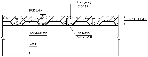
Illustration of slab decking.
BMB DECK is designed in 2 stages : first case is in construction, when reinforced concrete is not bearing the load, decking must carry the construction load as well as reinforced concrete and decking self-weight. Second case is in completed slab, which means reinforced concrete paticipates in carrying the live load as well as slab self-weight ; hence, decking and reinforced concrete work as composite slab. In second case, reinforced concrete must be designed to carry live load.
| Decking thickness | Coating mass | Moment of inertia | Section modulus | Live load on floor | Slab thickness | Maximum distance between joist |
|---|---|---|---|---|---|---|
| mm | g/m2 | Jx (cm4) | Sx (cm3) | (Kg/m2) | mm | m |
| 0.75 | Z120 | 46.57 | 1.82 | 500 | 120 | 2 |
| 0.95 | Z120 | 58.79 | 2.29 | 500 | 120 | 2.25 |
| 1.15 | Z120 | 70.93 | 2.77 | 1000 | 150 | 2.25 |
As transversal embossments distributted equally along longitudinal panel, upper concrete slab could not be slipped because of friction force. Studs is used to increase ability of adhesive strength and slip-agaisnt between decking and upper concrete slab, simultaneously, studs maintain combination of joist and decking slab behaviour as composite beam.
Studs are welded to steel beam by using a stud arc-welding machine. Connection area between studs and steel beam will be melted rapidly and the machine will press the studs down to this area. This process is supported by ceramic arc shield, called ferrule, which surrounds the connection to contain the melted metal and shield the arc.
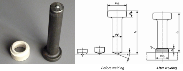
Stud and ferrule.
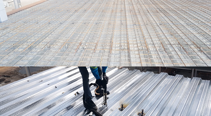
Reality decking and studs in construction site.
The decking is fastenned to steel beam by hexagonal head screw.
Fastener is always chose with sufficient threads to fully engage in the base metal. For attachments to 1/4” (6.35 mm) base steel, a self-drilling screw should have at least 1/4” (6.35 mm) of threads. It is helpful, but not critical, that the threads also engage in the material being fastened. The head of the fastener provides the bearing force for material being fastenned, while the threads provide the clamping force in base material.
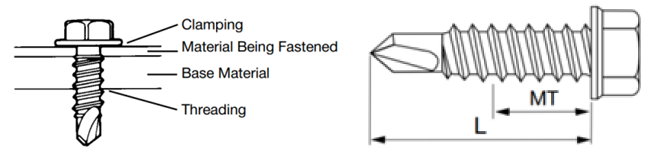
Illustration of screw.
| Screw Designation | Nominal Diameter (in.) |
Nominal Fastener Strength Section modulus | |||
|---|---|---|---|---|---|
| Tension, Pts lb (kN) |
Shear, Pss lb (kN) |
||||
| #6-20 | 0.138 | 1000 | (4.45) | 890 | (3.96) |
| #7-18 | 0.151 | 1000 | (4.45) | 890 | (3.96) |
| #8-18 | 0.164 | 1000 | (4.45) | 1170 | (5.20) |
| #10-12 | 0.190 | 2170 | (9.65) | 1645 | (7.32) |
| #10-16 | 0.190 | 1370 | (6.09) | 1215 | (5.40) |
| #10-18 | 0.190 | 1390 | (6.18) | 1645 | (7.32) |
| #12-14 | 0.216 | 2325 | (10.34) | 1880 | (8.36) |
| #12-24 | 0.216 | 3900 | (17.35) | 2285 | (10.16) |
| ¼ in. | 0.250 | 4580 | (20.37) | 2440 | (10.85) |
| Size | Min. Torsional Strength in-lb (Nm) |
|
|---|---|---|
| 6-20 | 24 | (2.7) |
| 7-18 | 38 | (4.3) |
| 8-18 | 42 | (4.8) |
| 10-12 | 61 | (6.9) |
| 10-16 | 61 | (6.9) |
| 10-18 | 61 | (6.9) |
| 10-24 | 65 | (7.3) |
| 12-14 | 92 | (10.4) |
| 12-24 | 100 | (11.3) |
| ¼-14 | 150 | (17.0) |
| ¼-20 | 156 | (17.6) |

