


PR CENTER
NEWSROOM
Welding symbols: Structure, types, and how to read them
01-04-2026
Table of content
Welding symbols play a crucial role in construction and fabrication drawings. These symbols ensure welders and engineers around the world interpret design details consistently, improving communication efficiency. In this article, BMB Steel will guide you through the structure, types of welding symbols, helping you understand how to read them correctly.
1. What are welding symbols?
Welding symbols are standardized graphical representations used in engineering and manufacturing drawings to convey essential details about welds and welding processes. They act as a universal shorthand system that describes the type of weld, its size, and other specifications. Thanks to these standardized symbols, engineers, designers, welders from different industries and regions can clearly understand the welding requirements for joints and connections.
Read more: Top 7 reputable pre-engineered steel building construction companies in Ho Chi Minh City
2. Basic structure of welding symbols
A welding symbol consists of 3 essential elements: the arrow, the reference line, and the tail. These parts form the foundation of any welding symbol, and each plays a distinct role that determines how the weld will be executed.
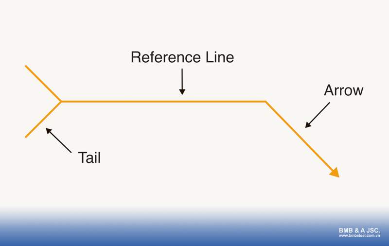
2.1. Arrow
The arrow connects the reference line to the welding joint and points directly to the location where the weld must be applied. It acts like a clear “Weld here!” indicator, ensuring precision and clarity in the welding process. Regardless of how many weld passes are required, each welding symbol always includes just one arrow that identifies the joint location.
2.2. Reference line
The reference line is a horizontal line that serves as the backbone of the welding symbol. It carries all vital details, such as the type of weld, joint design, weld size, weld pattern, etc. Essentially, it acts like a “blank line” on which engineers note down all the necessary information for the welder to follow.
When multiple welding operations are required, several reference lines may appear in one symbol. The line closest to the arrow represents the first weld pass, while the ones above it indicate subsequent passes. The reference line also helps define the weld orientation.
Read more: 13+ Modern popular industrial building drawings
2.3. Tail
The tail appears at the opposite end of the reference line from the arrow. It is used to include supplementary information that does not fit elsewhere in the symbol. This may include details about the welding process, filler material, electrode type, reference documents, or inspection methods.
If the weld is simple and no extra information is needed, the tail may be omitted to simplify the drawing.
2.4. The orientation of the weld
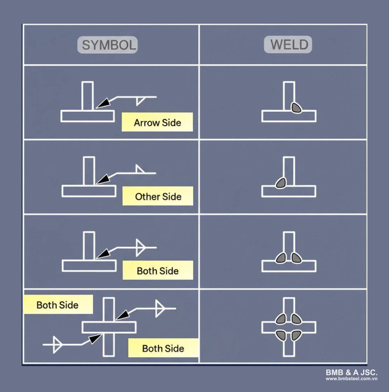
The placement of information above or below the reference line determines the side of the joint where the weld is applied. Information below the line (arrow side) indicates welding on the same side that the arrow points to. Information above the line indicates welding on the opposite side.
In some cases, engineers may specify welds on both sides of a joint or use the weld all around supplementary symbol to show that welding should be continuous around the part.
If the weld side is not important, the weld symbol element will be placed directly on top of the reference line
2.5. Numbers in welding symbols
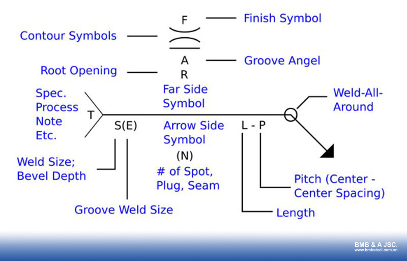
Numbers play a vital role in welding symbols, providing details about the size, length, spacing, and angles of welds.
- (S) – Indicates the size of the weld, depth of bevel, or required weld strength. These values determine the joint’s load-bearing capacity.
- (E) – Specifies the actual depth of penetration in groove welds.
- (L) – Represents the length of the weld when the entire joint is not welded.
- (P) – Denotes the pitch or spacing between welds (center to center) when multiple welds are applied to the same joint.
- (R) – Shows the root size or depth of metal filling for plug and slot welds.
- (A) – Refers to the groove angle, placed above or below the groove size, depending on the weld side.
- (N) – Indicates the number of spot, seam, projection, or slot welds on the arrow side of the reference line.
Read more: Standard industrial factory construction process
3. Types of welding symbols
There are many types of welding symbols used in engineering drawings, each representing a different welding method and joint preparation.
3.1. Basic weld symbols
Basic weld symbols form the foundation of all welding drawings. They indicate the type of weld to be performed and the preparation before welding.
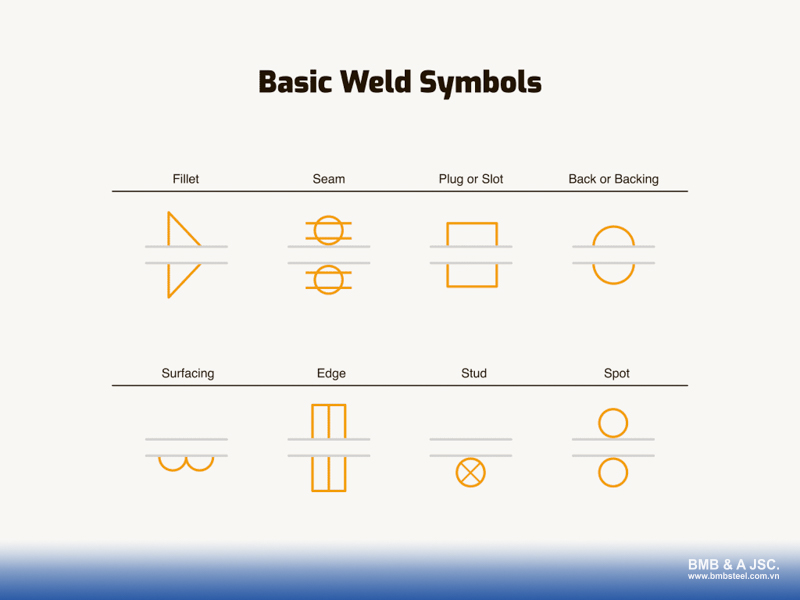
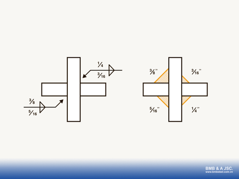
Fillet weld
The fillet weld is one of the most common types of welds. The symbol can appear on either side of the reference line or on both sides. If the symbols appear on both sides but are slightly offset, it indicates a staggered stitch weld pattern.
Plug or slot weld
Plug and slot welds are used to join overlapping metal pieces. Their symbols can be placed on either side of the reference line, but not on both sides.
For plug welds, the symbol includes details such as the diameter of the weld, the number of welds, and the center-to-center spacing.
For slot welds, the symbol specifies the number of slots, the width and length of each slot, and the spacing between them.
Spot or projection weld
A spot weld joins two overlapping metal sheets without the preparation required for plug or slot welds. These welds are commonly performed on sheet metal using a spot welding machine or TIG welder.
Similar to plug welds, the symbol does not appear on both sides of the reference line. It may also appear in the middle of the line, meaning the weld side is not significant.
Stud weld
Stud welding fuses a metal stud onto the surface of a metal plate using a stud welding gun. The symbol specifies the stud size, number of studs, and spacing between them. You will only find this symbol on the arrow side of the reference line.
Seam weld
Seam welding is a type of resistance welding used to create a continuous weld along the joint, often for sheet metal. Its symbol cannot appear on both sides of the reference line, but it may be placed in the middle, indicating no specific side significance.
Back or backing weld
Although the symbol for a back weld and a backing weld looks the same, they differ in application. A back weld is performed after the main weld, while a backing weld is made before it. The tail of the welding symbol provides clarification on which one is required. The back or backing weld symbol appears on the opposite side of the reference line from the main weld symbol.
Surfacing weld
Surfacing welds are used to apply one or more layers of metal onto a surface to improve wear resistance or restore dimensions. If a dimension is indicated, it refers to the minimum height of the weld bead. These symbols are shown only on the arrow side of the reference line.
Edge weld
An edge weld is typically used for sheet metal where the edges of two parts are joined. The weld size, if noted, represents the depth of penetration, not the bead size. Edge weld symbols can be placed on either side or on both sides of the reference line.
Read more: What is the pre-engineered steel building? The optimal solution for your projects
3.2. Groove weld symbols
Groove welds are among the most common weld types in structural fabrication, used where two metal pieces meet edge-to-edge. The groove weld symbol can appear on either side of the reference line, depending on the location of the weld. Each type of groove weld symbol represents a different joint preparation and welding requirement.
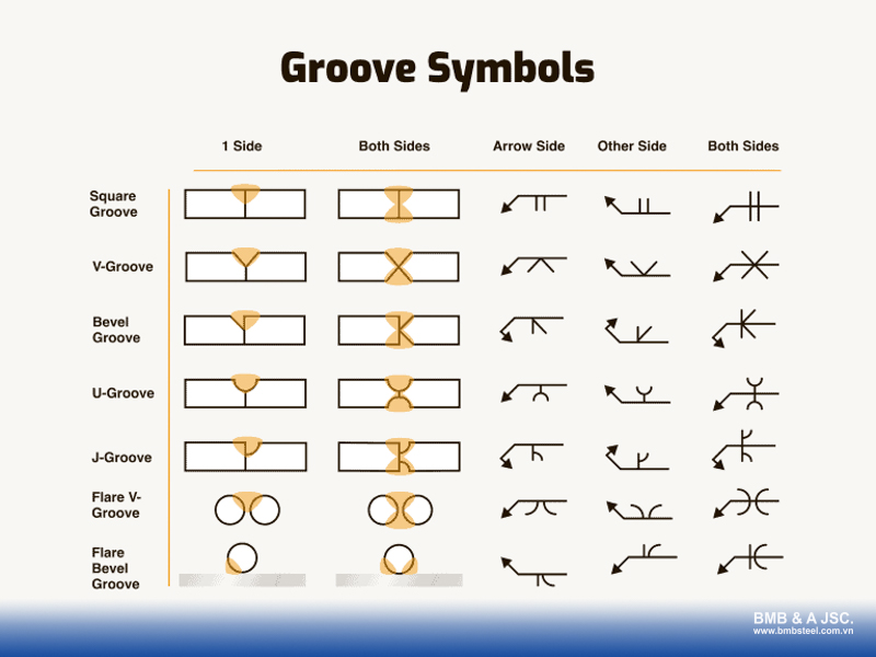
V-groove welds
V-groove welds involve bevels cut on both sides of the joint. The plate edges are cut at an angle, and a number above the symbol may show the included angle between the bevels.
Bevel groove welds
Bevel groove welds have a bevel on only one side of the joint. The arrow points to the side that must be beveled, and an angle above the symbol indicates the bevel angle.
U-groove welds
U-groove welds feature a rounded, concave joint preparation, providing more space for the weld to penetrate. They are less common and more expensive to prepare since the edges must be machined.
J-groove welds
J-groove welds are similar to bevel welds but have a curved J-shaped preparation. Like U-groove welds, they are machined and used when deeper penetration is required.
Flare V-groove welds
Flare V-groove welds appear when welding two rounded surfaces, such as hollow structural sections (HSS). The radius of the tubes forms a natural V-shaped groove, and the symbol may specify the required penetration depth.
Flare bevel groove welds
Flare bevel groove welds occur when welding a round piece (like a rod or pipe) to a flat plate. The weld needs no special preparation, though the symbol may indicate the desired penetration depth.
4. How to read fillet welding symbols
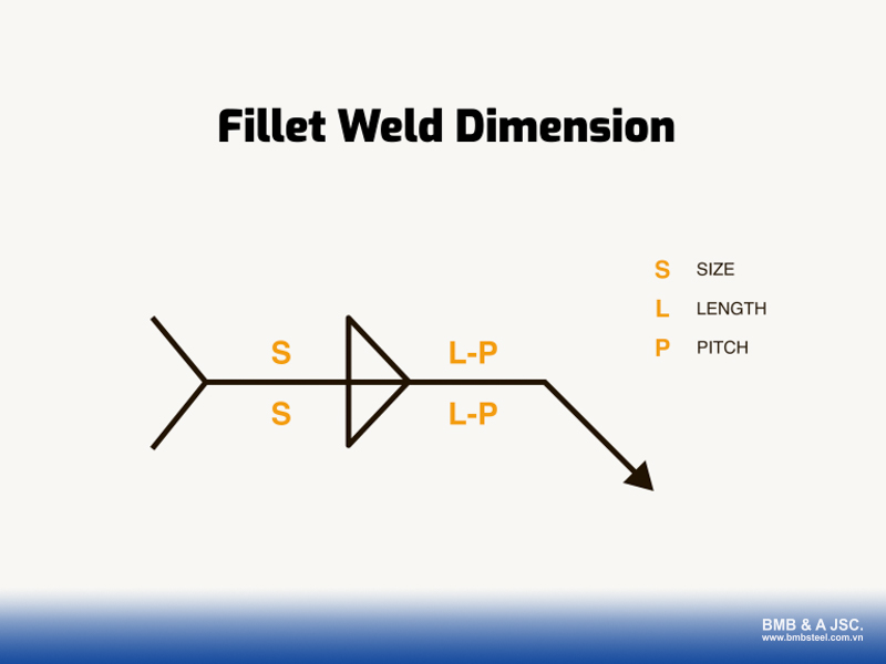
On the left side of the fillet weld symbol is the weld size, represented by the letter “S”. The weld size indicates the leg length of the fillet weld. For instance, a ⅜” fillet weld means that both legs of the weld measure ⅜ inch from the plate to the toe.
If no weld size is specified on the symbol, the weld size defaults to the thickness of the thinner plate being joined. To verify the weld dimensions, welders typically use a fillet gauge to check that the weld size meets the design requirement.
On the right side of the fillet weld symbol, you’ll find information about stitch welds, including their length (L) and pitch (P): The length (L) indicates the length of each stitch weld. The pitch (P) specifies the center-to-center spacing between consecutive stitch welds.

If the fillet weld symbols appear slightly offset from one another on both sides of the reference line, this indicates a staggered stitch weld pattern. When nothing is listed, the weld is considered continuous along the joint.
5. How to read groove welding symbols
Groove welding symbols provide detailed information about how a joint should be prepared and welded. They indicate the type of joint preparation, the groove angle, depth of preparation, depth of penetration, and the root opening.
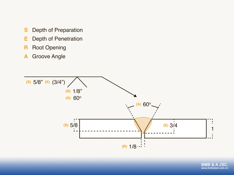
Above is an example of the structure of a groove weld. The root opening (R) is shown inside the symbol, while the groove angle (A) is displayed below it. The groove angle represents the included angle of the joint, not the individual bevel angle. For example, a 60° included angle means each plate has been beveled at 30°.
On the left side of the groove weld symbol is the depth of preparation (S) and the depth of penetration (E). The depth of preparation measures the distance from the top surface of the plate down to the end of the groove or bevel. The depth of penetration, shown in brackets, indicates how deep the weld metal extends from the plate surface to the root of the weld.
6. CJP and PJP

In welding, every joint can be classified as either a complete joint penetration (CJP) or a partial joint penetration (PJP) weld.
A CJP weld, often referred to as a 100% weld, requires the weld metal to fully penetrate the entire thickness of the joint, leaving no gaps or unfilled areas between the plates. To specify a complete joint penetration weld, the engineer will mark “CJP” in the tail of the welding symbol.
In contrast, a PJP weld does not require full penetration to the root of the joint. PJP welds are less common.
7. Supplementary symbols
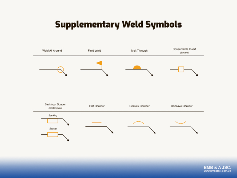
In addition to basic weld symbols, several supplementary symbols provide extra details that are essential before fabrication. Understanding them ensures proper sizing, finishing, and quality of the weld. Here are the most common supplementary welding symbols:
All around
Represented by a small circle where the reference line meets the arrow. It indicates that the weld should go all around the joint.
Field weld
Shown as a flag at the junction of the arrow and the reference line. It means the weld must be performed on-site. If this symbol is absent, the weld should be done in the shop.
Melt-through
Depicted as a black half-circle placed opposite the weld symbol. It specifies that the weld metal must penetrate completely through the joint, creating visible fusion on the backside.
Consumable insert
A square symbol opposite the weld symbol, showing that a metal insert will be consumed during welding.
Backing
Indicates the use of a backing bar or backing weld to achieve full penetration. If the backing is removed after welding, the symbol includes the letter “R”.
Spacer
Similar in appearance to the backing symbol, but it is placed in the middle of the reference line.
Flat/Convex/Concave contour
These symbols define the final shape of the weld surface. Alongside the contour, a finishing letter shows the method used to achieve that finish:
- C – Chipping
- M – Machining
- G – Grinding
- H – Hammering
- P – Planishing
- R – Rolling
- U – Unspecified
Welding symbols are essential elements that ensure consistency and clarity in technical drawings. Engineers and welders with a solid understanding of welding symbols can work more efficiently, ensuring precision and safety for the entire structure.
If you are looking for a professional steel structure contractor, contact BMB Steel today. With over 20 years of experience in the pre-engineered steel building industry, we are committed to delivering durable, internationally certified steel structure solutions.

2 months ago
Learn about one-way and two-way strip foundations, their differences, pros and cons, and considerations for choosing the right solution for your project.

1 year ago
Discover the growing demand for steel structures in global construction. Learn about steel structure types, advantages, and key applications.

2 months ago
An overview of commonly used heat-resistant roof materials, such as tiles, insulated metal roofing, etc., which are suitable for various types of buildings.

2 months ago
What is an EPC contract? Learn how EPC contracts work, contracting strategies, the role, pros, cons of EPC contractors and differences between EPC and EPCM.
6 months ago
What is a bolt? Learn about bolt structure, classification, applications, how to choose bolts that meet technical standards in construction and engineering.
Comment
(0)


Building pre-engineered steel buildings is the trend of today. Every pre-engineered steel building project needs to have a complete and detailed steel structure drawing, then the finished product will meet the requirements.
Pre-engineered steel buildings are composed of different elements connected through connection systems. This article will discuss the differences between flexible connections and rigid connections.
Structural steel is an indispensable factor in the construction of pre-engineered steel buildings. To complete a project with high standards, the load-bearing steel frame structure is essential to focus on.
Learn about one-way and two-way strip foundations, their differences, pros and cons, and considerations for choosing the right solution for your project.
Pre-engineered steel buildings are increasingly popular by virtue of their advantages, such as optimizing construction costs, short construction time, etc. Parallelly, owners are also concerned about some problems. In this article, BMB Steel will provide you with helpful information about construction standards and the acceptance of pre-engineered steel buildings.

There are a number of steel buildings constructed and in use. The writing below shall give you an overview of some impressive steel structure projects in Vietnam.

